


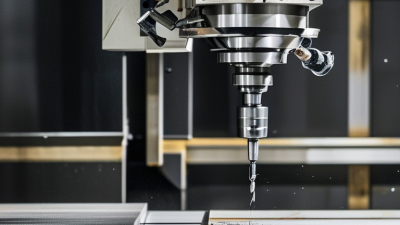
A Compact 5 Axis Cnc Machine brings five-direction cutting into a smaller workshop footprint. It can tilt and rotate the workpiece while the cutting tool removes material from several angles. This movement reduces repeated setups, improves tool access, and supports complex parts with curved surfaces, deep cavities, and angled holes.
The word “compact” does not mean simple. A small machine still needs a rigid frame, accurate rotary axes, reliable control software, and careful thermal management. A machine may fit beside two operators, yet vibration can still damage surface finish. That detail is often overlooked.
Peter Zelinski, editor-in-chief of Modern Machine Shop, has explained the practical value of five-axis machining as “access to the part,” rather than motion alone. His observation reflects an important manufacturing principle. More axes only create value when programming, fixturing, and operator knowledge work together.
In real production, an engineer may secure an aluminum housing once, then machine its sides, ports, and blended contours without moving the fixture. That can reduce alignment errors and shorten handling time. However, it does not guarantee better results. Poor post-processing, weak workholding, or an unsuitable toolpath can waste the machine’s advantages.
This guide examines what a Compact 5 Axis Cnc Machine is, how its axes function, and where it fits in modern manufacturing. It also considers limitations, including cost, training, maintenance, and programming complexity. The technology is powerful. It is not magic. Careful evaluation remains essential before purchase.
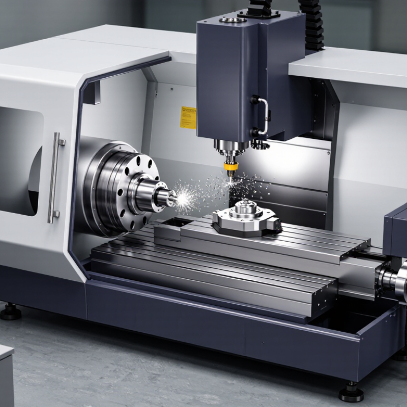
A compact 5 axis CNC machine is a computer-controlled cutting system with five coordinated movement axes. Three axes move linearly along X, Y, and Z. Two rotary axes tilt or turn the workpiece, tool, or spindle. This arrangement allows the cutter to reach several surfaces in one setup. Fewer setups can reduce alignment errors and handling time.
Compact means a smaller working envelope, not limited capability. A serious machine should provide rigid construction, accurate rotary tables, thermal control, reliable probing, and effective chip evacuation.
In a crowded workshop, its footprint matters. So does operator access. A machine that saves floor space but restricts loading may create new delays. That detail is easy to overlook.
Industry data supports the demand for advanced machining. Grand View Research valued the global CNC machine market at about 83.99 billion dollars in 2023. It also projected continued growth through 2030. This trend reflects wider use of precision components, medical parts, aerospace structures, and complex molds.
Yet market growth does not guarantee good results. A compact 5 axis machine still needs suitable spindle power, balanced fixturing, and verified post-processing. Poor toolpath control can cause collisions or uneven surfaces. Smaller is not automatically better. Hands-on trials remain essential before purchase.


North of Industrial Road, Linqing Economic Development Zone,Liaocheng City, Shandong Province, China
w.eric@lucimagnet.com
Eric: 0086-15688878114
Surface Grinder Machining Center CNC Lathe Machine Boring and Milling Machines
Semiconductor Optics Automobile Molding Construction Machinery Shipping Aerospace Valve Industry Wind Power Industry Abrasives Industry Refractory Industry Ceramic Seal Industry Bearings Industry
Company Patent Certificates Factory Tour Team Member Our Partner Our History Real-time Factory Inspection R&D Strength Terms & Conditions Privacy Statement


© 2025 Shandong Linmo CNC Machine tool Equipment Co.,Ltd. All Rights Reserved.

